
Electric Hammer
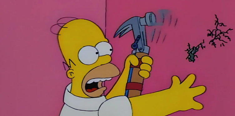
Some projects start with a very serious problem. This one started with a ridiculous question: What if Homer Simpson’s electric hammer actually existed?
In The Simpsons, Homer’s electric hammer is one of those absurd inventions that feels funny because it is both completely unnecessary and strangely believable. It is a tool designed to solve a simple problem in the laziest way possible: hammering without having to move your arm.
So naturally, I wanted to build it.
The goal was not only to create a prop that looked like the object from the show, but to design a real functional prototype using 3D modeling, mechanical design, electronics, and 3D printing.
The idea behind the project
The challenge was simple to explain, but not so simple to build:
Could I design a 3D printed mechanism capable of moving a hammer back and forth automatically?
This meant the project needed to combine several elements:
A recognizable design inspired by the original cartoon invention
A functional mechanical system
A motorized movement
A strong enough structure to hold the mechanism
3D printed parts that could be assembled and tested
A final object that looked fun, absurd, and functional
This is exactly the kind of project I love: taking an idea that should probably stay fictional… and trying to make it real anyway.
Designing the hammer in SolidWorks
The first step was to transform the idea into a 3D model.
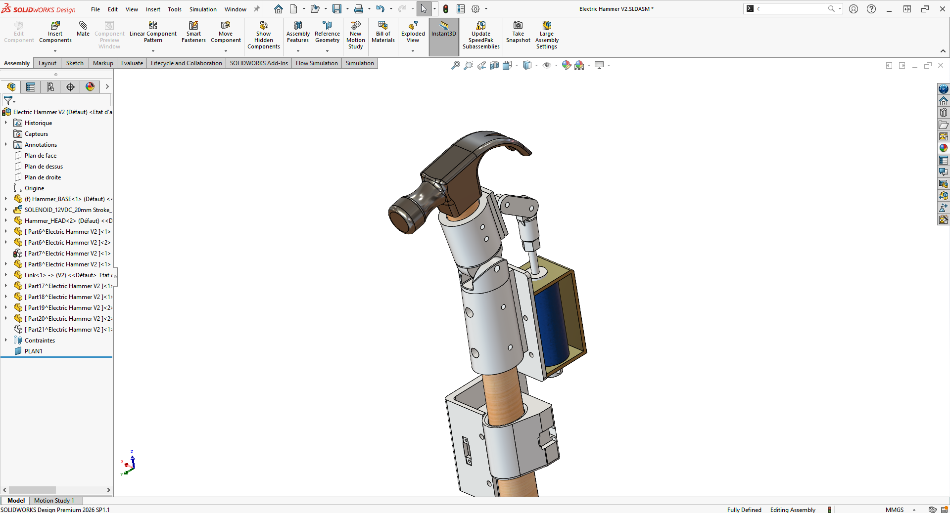
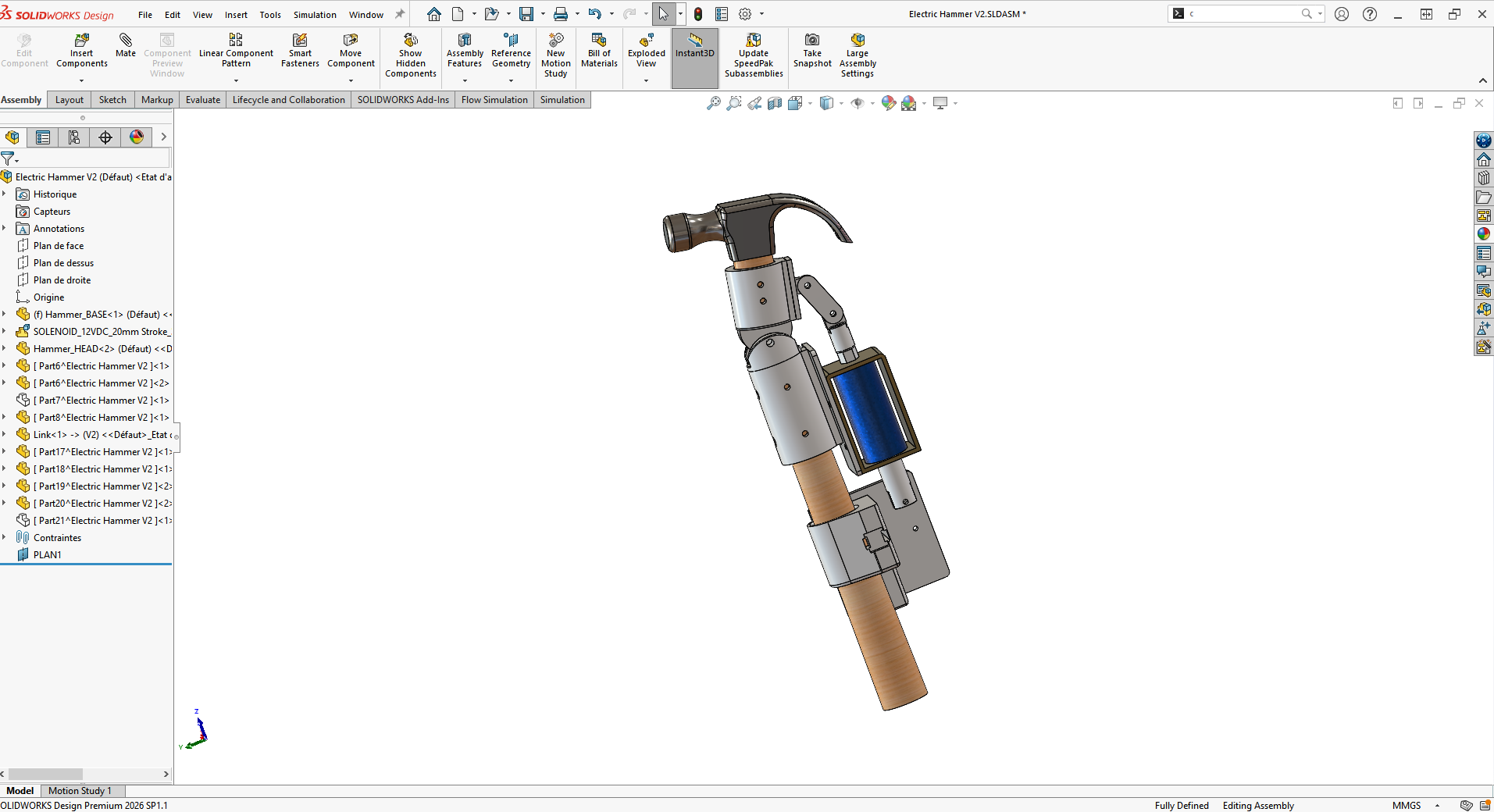
I designed the project in SolidWorks, using CAD to define the proportions, internal space, mechanical movement, and assembly structure.
For a project like this, the 3D model is much more than a visual preview. It is the place where the mechanism starts to make sense.
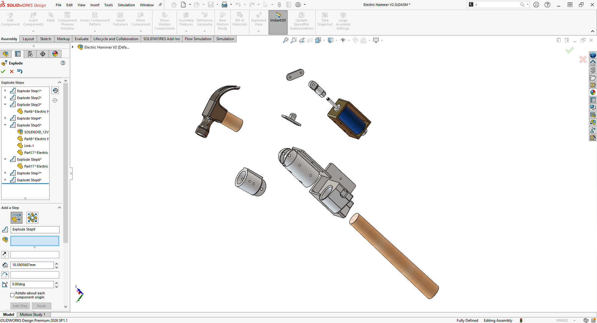
I had to think about how the hammer would move, where the motor would be placed, how the parts would connect, and how the structure could be printed and assembled without becoming too fragile or too complicated.
This is where 3D modeling becomes extremely useful: before printing anything, I could already test the general layout, check clearances, and prepare the design for fabrication.
Building a functional mechanism
The most important part of the project was the movement.
A static prop would have been fun, but the real challenge was to make the hammer actually work. The mechanism had to convert motor rotation into a repeated hammering motion.
This required several rounds of design, printing, assembly, and testing. Like many functional prototypes, the first version was not perfect. Some parts needed more strength, some dimensions needed adjustment, and the movement had to be refined until it felt convincing.
That is one of the biggest advantages of 3D printing for mechanical projects: it allows fast iteration. Instead of waiting weeks for manufactured parts, I could modify the design, print a new version, and test it again.
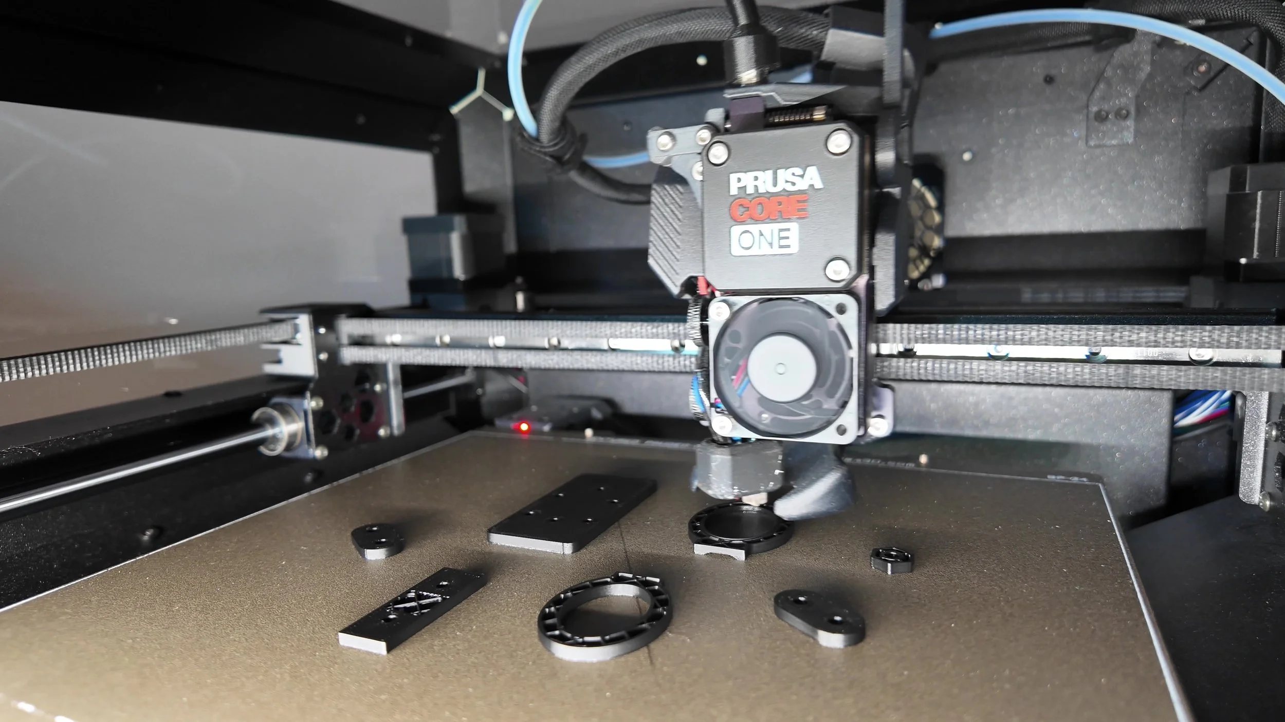
3D printing the parts
Once the main design was ready, the parts were prepared for 3D printing.
The project included both external pieces, which defined the look of the hammer, and internal mechanical parts, which had to support the movement and assembly.
For a functional prototype, print orientation, wall thickness, tolerances, and material choice matter a lot. The goal was not just to print something that looked good, but to create parts that could survive testing and movement.
This is where 3D printing becomes more than a visual tool. It becomes a real prototyping method for mechanical design.
Assembly and testing
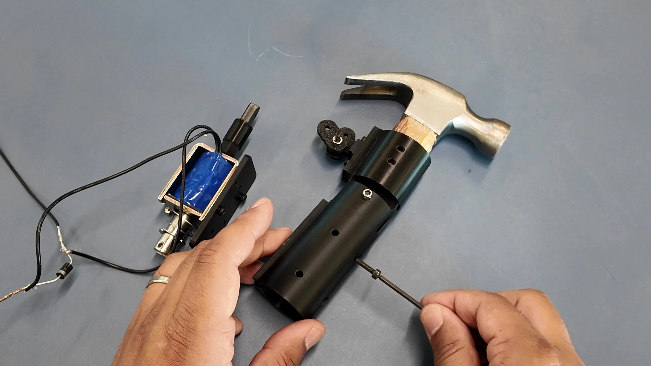
After printing, the next step was to assemble everything and test the mechanism.
This is usually the moment where the project tells you the truth.
A design can look perfect on screen, but once the parts are printed and moving together, small problems become very obvious: friction, alignment, weak areas, limited space, or parts that need a small redesign.
The electric hammer went through this same process. It needed testing, adjustments, and improvements before reaching a version that worked properly.
That trial-and-error process is not a failure. It is the normal path of prototyping.
Final result
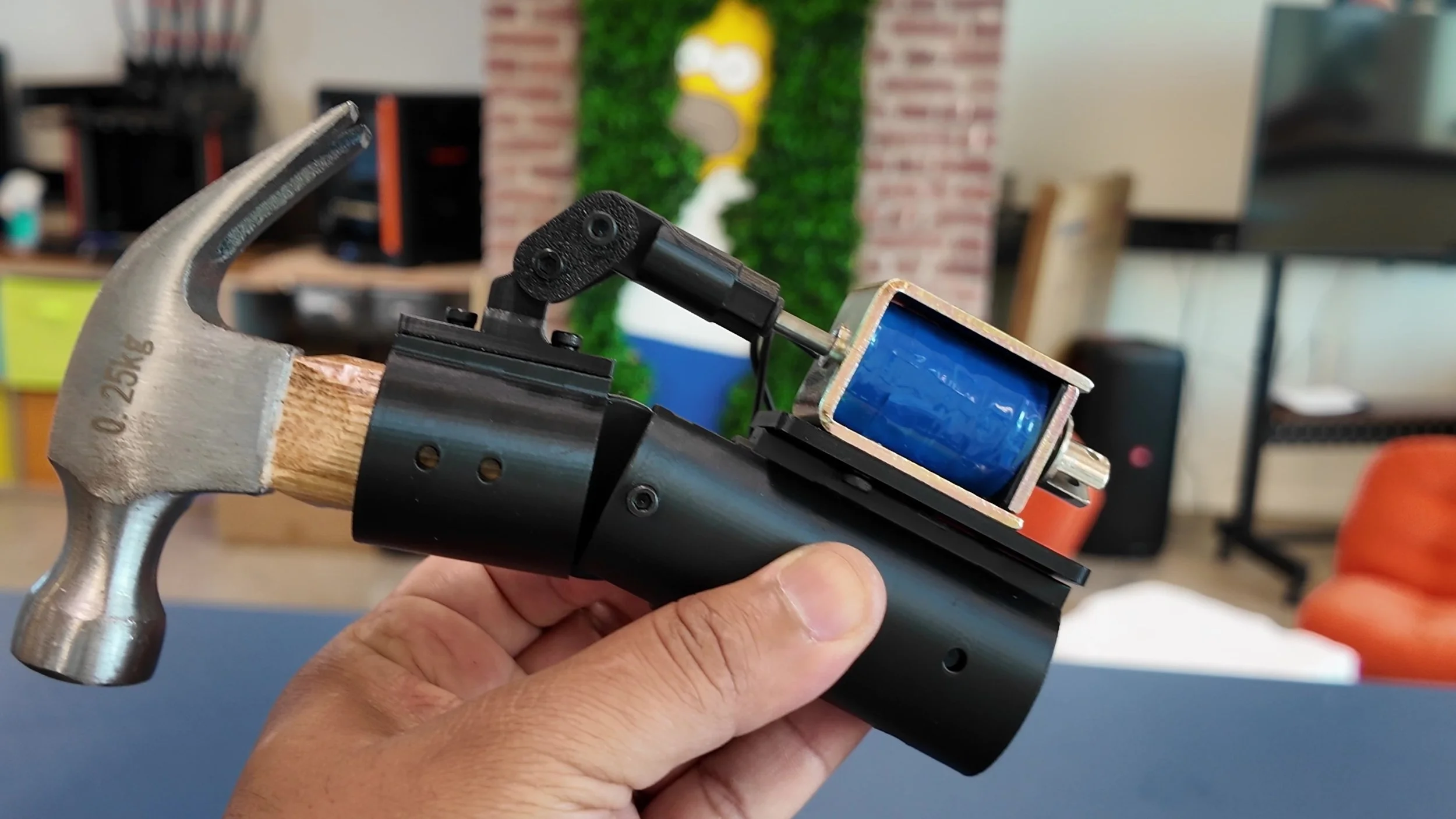
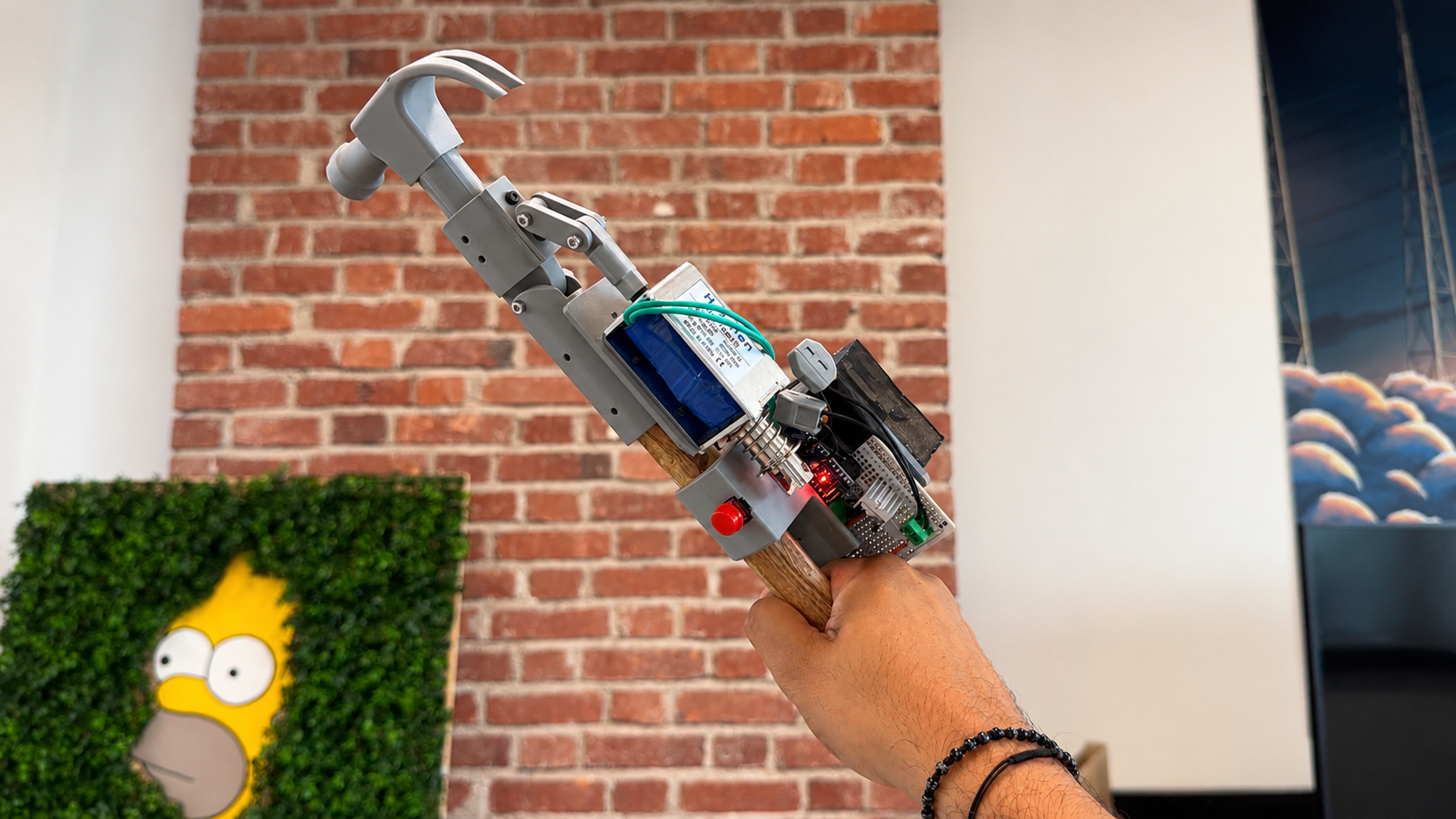
The final result is a 3D printed functional prototype inspired by Homer’s Electric Hammer.
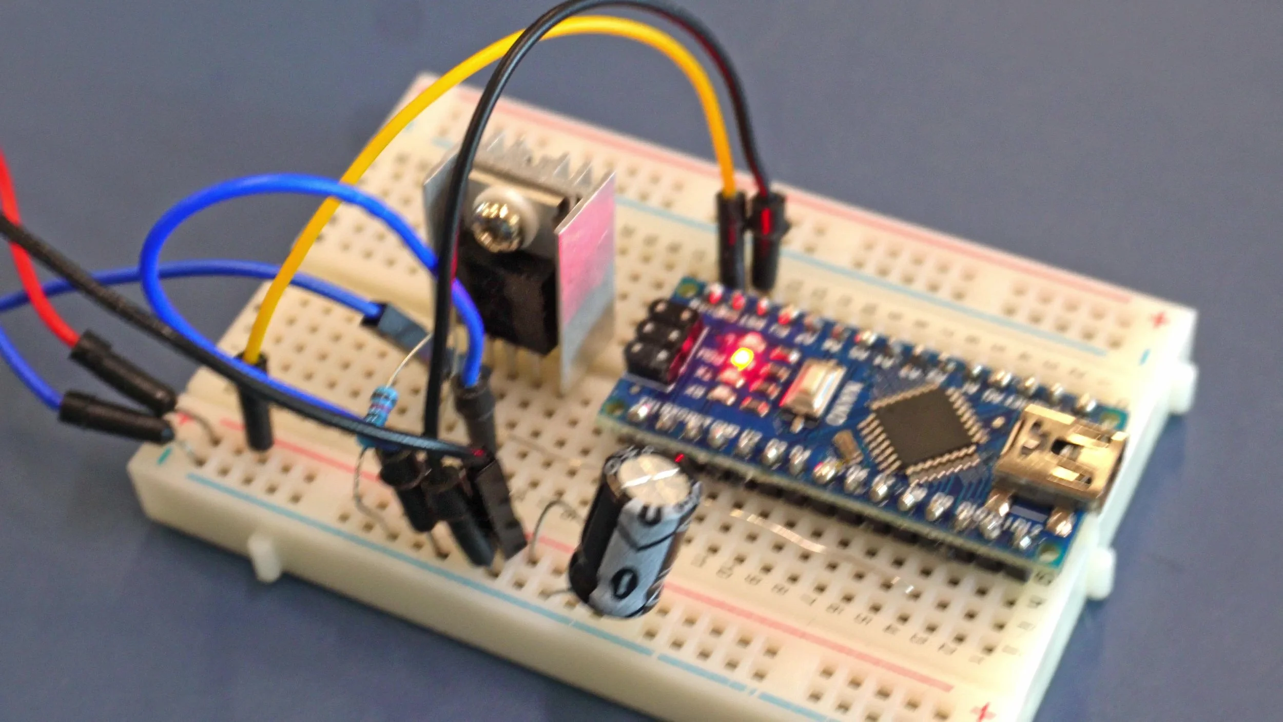
It combines a cartoon-inspired idea with real mechanical design, electronics, and 3D printed parts. It is silly, unnecessary, and exactly why it is fun.
But beyond the joke, this project is also a good example of what can be done with 3D printing and CAD design: turning an imaginary object into a physical mechanism.
From the outside, it looks like a funny prop. Inside, it is a small mechanical design challenge.
Why this kind of project matters
Projects like this may look playful, but they are also a great way to demonstrate real technical skills.
To build something like this, you need to combine:
3D modeling
Mechanical design
Functional prototyping
3D printing
Assembly
Testing and iteration
Problem-solving
The same process can be applied to many serious projects: custom tools, mechanisms, product prototypes, workshop devices, educational models, and proof-of-concept machines.
Sometimes, the best way to show engineering know-how is to build something fun enough that people actually want to look at it.
Need a custom prototype or mechanical design?
Do you have an idea for a custom object, mechanism, prototype, prop, or functional 3D printed part?
We can help you turn it into a real object through 3D modeling, SolidWorks design, 3D printing, assembly, and testing.
From a simple idea to a working prototype, we can help bring your project to life.